Sep 05, 2025
A Cool Wing
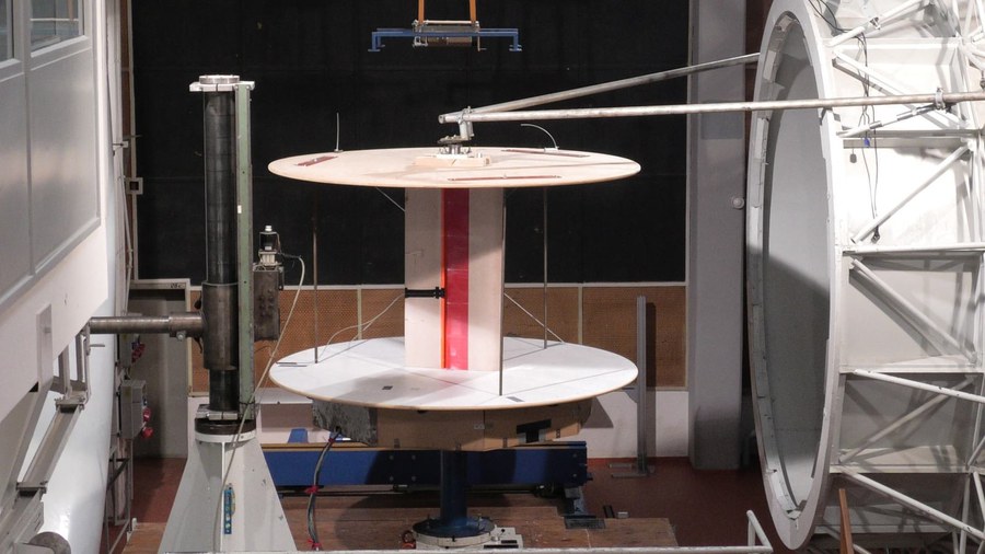
Wing model with internal heat exchanger in the wind tunnel
The subject of a research project, in which both the Chair of Aircraft Engineering (LFT) and the Chair of Flight Mechanics and Control (FMR) are involved, concerns the accommodation of heat exchangers in the wing, e.g. for cooling fuel cells for electrically powered aircraft. The current configuration provides for a slotted-wing arrangement, in which the heat exchanger is located in a strongly widened gap and where the air flows through it.
Last week, wind tunnel tests were carried out on a previously numerically optimized contour. Of particular interest is the effect of the pressure loss caused by the heat exchanger on lift and drag of the airfoil, especially in comparison to a conventional radiator outside the wing. Finally, an internal heater was put into operation to get a first impression of the further changes caused by the heat load of the cooler.
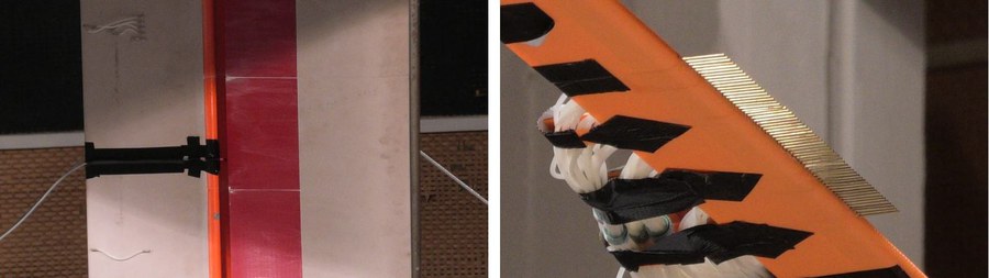
Thermometer for measuring the temperature of the air exiting from the radiator (left), large Pitot rake for wake measurement (right)
A new pitot calculator was used to measure the resistance. With a total of 60 pressure tubes, it can cover the entire wake of a wing profile at once.
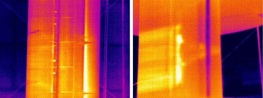
Infrared images of the wing's suction side; left without, right with internal heating (flow from the right)
The case without internal heating (left) clearly shows a laminar separation bubble with turbulent reattachment in the area of the main pressure rise. This is interrupted by two clearly visible turbulent wedges. With heating, the warm airflow emerging from the "cooler" is clearly visible on the surface.
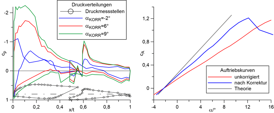
Pressure distributions for various angles of attack (left), lift curves without and with blockage correction (right)
The lift can be calculated from the pressure distributions (left) determined by holes embedded into the contour. After correction of the wind tunnel blockage by the model, the lift curve of the airfoil is obtained (right, blue line). The difference to the theoretical lift slope (gray line) shows the effect of the pressure loss in the gap on the downstream area of the airfoil.