Jul 22, 2025
Measurement of winglets in the wind tunnel
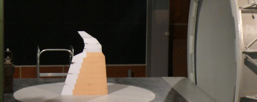
Truncated wing model with winglet in the test section
Last Thursday, a thoroughly informative measurement campaign came to an end in the wind tunnel. The topic of a student research project was the evaluation of the aerodynamic potential of winglets. The starting point of the consideration is the fact that a winglet interacts with the lift distribution over the entire wingspan, which requires a very small scale in the wind tunnel, but the viscous flow around the end area would then no longer be correctly mapped. The approach pursued here is based on a much shorter inner wing with a greatly increased chord length, which generates the same lift distribution in the outer area as the original wing. Thus, since the replacement wing has only about 15% of the wingspan of the original wing and a half-model structure is used, the winglet can have almost the original size and be measured under realistic flow conditions.
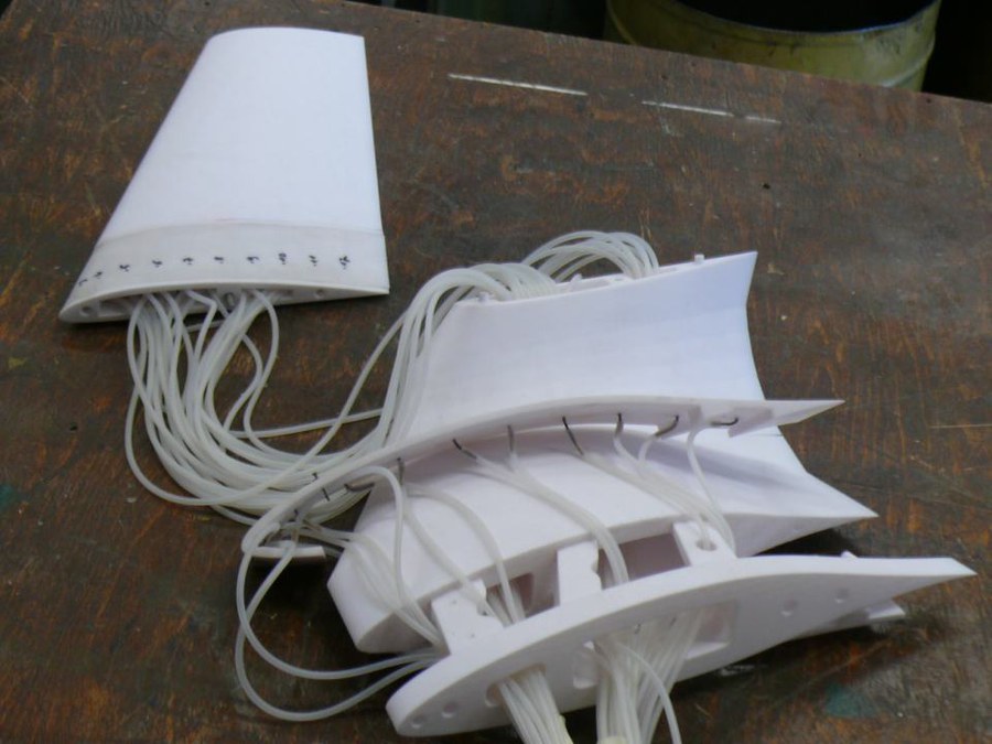
Winglet with junction to wing, pressure taps and -hoses
Extensive experience was gained during model construction: The truncated inner wing consists of milled segments stacked in the spanwise direction with a 3D-printed trailing edge area; the outer wing including the winglet is composed entirely of printed segments. Two rows of pressure taps are embedded in the surface. However, the structure proved to lack stiffness, so that the winglet tip had to be supported against the turntable with a rod.
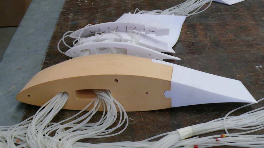
Upmost wing segment with juction to winglet and pressure hoses
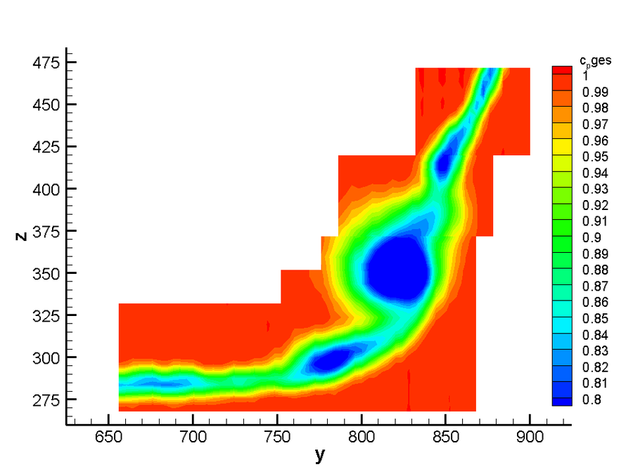
Wake bucket of the winglets at 5 deg anle of attack and 30m/s flow velocity
The results of the measurements evaluated so far show clear effects of the three-dimensional flow around the wing, which cannot be predicted using simple design methods (lifting line and 2D profile calculation). In one segment, there is even a flow separation that is clearly reflected in the wake. In general, a large sweep angle appears to be directly causing in increased profile drag.
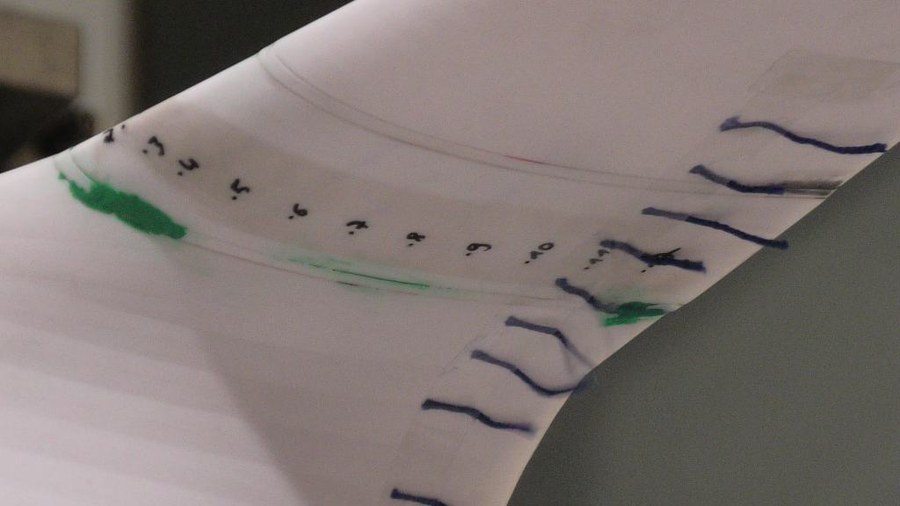
Flow separation on the Winglet at 5 deg angle of attack, visualized by wool tuft
Thermographic images show turbulence wedges at some gaps between the segments, but not at all and only at certain angles of attack, so that this type of structure appears to be controllable in principle.