Large Low Speed Wind Tunnel
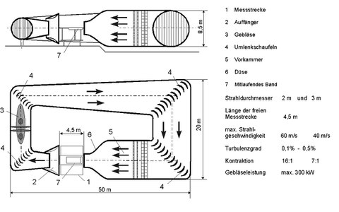
The large wind tunnel is of the Göttingen Type with a closed curciut, but it has an open test section. This allowes for best possible access to the test objects, particularily concerning flow visualization.
The air duct consists of a tube made of reinforced concrete. The total length of the curcuit is about 110 m. Only the interchangable nozzle, the collector and the guide vanes are made of plywood. The nozzle has a circular cross section with a diameter of 3 or 2 m, respectively. The largest cross section within the settling chamber is 8 m of diameter, resulting in a contraction ratio of 7:1 or 16:1. Together with honeycomb and two screens this guarantees a very uniform mean flow. The turbulence level is well below 0.5%.
The tunnel is powered by a two-stage axial compressor. The counter-rotating stages with 7 und 5 blades are made of wood like classic propellers. Two 150-kW-DC-motors are directly coupled to the rotors. Rotor speed can be varied continously up to 400 rpm via thyristor control. Maximum flow velocity is 40 or 60 m/s, respectively.
Test Section Configurations
- Open Jet
According to the originally intended purpose of the tunnel, the standard configuration of the test section is open in all direction. This way, flow conditions are similar to those an airplane experiences at altitude. - Rigid Floor
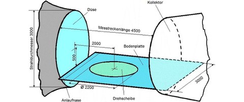
A ground plate can be istalled into the test section for measurements with vehicles of all types, reaching from container ship to athletes on sleds. Moreover, the ground plate can be used as a symmetry plane for half model measurements with respective aircraft models. Unlike most automotive wind tunnels, the ground plate has its own leading edge due to the circular nozzle. Nontheless, the model is positioned relatively far upstream in order to prevent the boundary layer on the ground from growing to much.

Aufbau für Fahrzeugaerodynamik mit festem Boden
- Atmospheric boundary layer
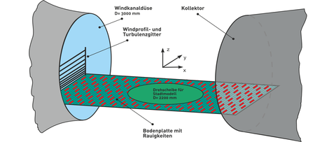
The atmosperic wind field is not a calm and uniform flow. Instead, it is a very thick, highly turbulent boundary layer, due to the long distances and roughness of the earth's surface. In the wind tunnel, this condition is reached by a grid within the nozzle that causes a distortion of the velocity profile by uneven blockage and increases turbulence. Furthermore, roughness elements on the ground keep up a high turbulence level in the lowest layers. In this case, the model is positioned more downstream and the ground plate reaches into the nozzle to lengthen the running distance for the boundary layer to evolve.

Aufbau für atmosphärische Grenzschichtmodellierung
- Moving Floor
When investigating very low-flying objects or the underflow of vehicles, it is often not sufficient to operate with a fixed ground plate. A boundary layer is formed there, while in reality the ground passes under the vehicle at approximately the inflow velocity. Measures in the underbody area sometimes even show opposite effects depending on compliance with the ground boundary condition. The wind tunnel is equipped with a fabric belt that runs over two cylindrical rollers. It has a length of 3500mm and a width of 1800mm and can run at up to 30m/s.

