Process Modelling and Simulation
In addition to the dimensioning of engineering structures the comprehension of manufacturing and forming processes is essential for the development of innovative lightweight products. Often, numerical investigations are the only possibility to get insight into the complex relations between the structure and the process parameters. Hence, one focus of the Chair of numerical and Experimental Solid Mechanics is the modelling and simulation of joining and forming processes. In addition to a load-optimised process design, the potential of weight and energy reduction are of interest.
Simulation of riveting process of hybrid materials
The self-piercing riveting process is a mechanical joining process without an initial hole. It is characterised by a high reproducibility and a well-engineered process monitoring for different material combinations. Thereby, the selection of the right joining parameters is crucial to obtain a high-quality joint. The non-linear orthotropic material behaviour of fibre-reinforced composites is determined by the complex damage behaviour and their modelling is a challenging task. In a research project on the Chair of Numerical and Experimental Solid Mechanics a model for ABAQUS EXPLICIT was developed to simulate the self-piercing riveting process. It based on a multiscale approach to predict the effective orthotropic composite properties and distinguish between intra- and interlaminar damage modes.
Draw Bending
Draw Bending is a process used for producing beam-shaped profiles. There is an industry-oriented and production-oriented technology demonstrator and a small sliding bending machine for teaching purposes located at the institute. Draw Bending as a forming process as well as the tools as active elements are continuously developed further via software simulation.
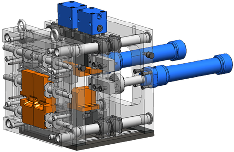
The demonstrator is modular and consists of the basic unit, the guide and greasing unit, the gripper and feed unit, the hydraulic unit, the tool unit and the control unit. The demonstrator can be upgraded with additional modules, such as a reel for feeding the material, a straightening unit, variable speed motors for the active elements of the tool and a cut-to-length and storage unit.
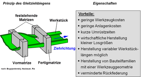
With the procrss of draw bending, beam-shaped cold profiles can be produced in virtually any desired length in an effective manner. The figure shows the principle of draw bending. A sheet blank, as a single sheet or a coil, is drawn by means of a drawing device by means of forming matrices. Thus, the blank is converted into the profile geometry predetermined by the matrices. By means of draw bending, profiles with symmetrical cross-sections (U-profiles, C-, Z- and hat profiles) can be produced effectively in different material thicknesses and in non-standard dimensions (intermediate sizes) and small piece numbers. The draw bending represents an extension or supplementation to other profiling methods such as, for example, roll profiling.

Tool and feed unit

Werkzeug- und Vorschubeinheit
The main part of the demonstrator "GZB 5.0" is the adjustable tool unit as well as the following gripping unit, which is responsible for the quasi-continuous drawing process.
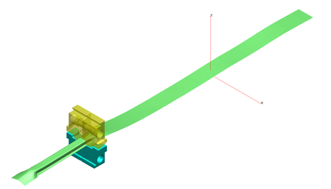
The numerical simulation (FE simulation) is now a proven tool for the effective generation of forming tools. By means of simulation, the tools can be tested and optimized in advance before the capital-intensive construction, which guarantees quality-oriented components. This is particularly true for draw bending as a relatively unknown method. In this case, the tools must be optimized and tested by means of simulation before they are produced, since new component geometries are necessary with each new profile geometry to be generated. Furthermore, the flow behavior also changes significantly. The simulation also provides a better and deeper look into the specific sliding-bending process, which is significant for further development. A selected example of the deformation simulation of draw bending is shown in the following figure.

Simulation of a hat profile
