Staub I
Table of contents
|
STAUB I – Investigations on the safety relevant aspect of dust release in gas cooled high temperature reactors with focus on the required experiments |
| Project manager: |
Prof. Dr.-Ing. habil. Antonio Hurtado |
| Contributor: | Dipl.-Ing. Martin Lustfeld |
| Duration: | 09/2009 - 03/2011 |
| Funding: | BMWi |
| Cooperations: |
|
Brief Description
|
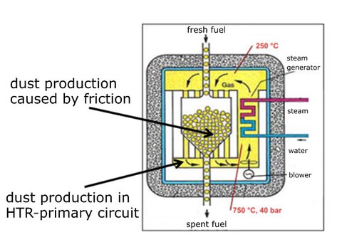
In a Pebble Bed High Temperature Reactor (HTR), the reactor core consists of a large number of spherical graphite fuel elements. The pebbles are loaded into the reactor core as a packed bed with conical floor. During operation, the pebbles move through the core from the top to the bottom end. Due to this overall movement in the pebble bed, relative movements between pebbles and reflector (graphite) as well as between pebbles among each other are unavoidable. This slow and continuous movement generates different types of graphite particles. Additionally, carbonaceous particles can be produced by chemical reactions. All these particles are dispersed in the helium coolant and transported throughout the primary circuit. During severe accidents such as the Depressurized Loss of Forced Coolant (DLFOC) radioactive contaminated dust can be remobilized and released to the environment. Based on the safety relevance of this topic, the aim of STAUB-I is to build an integral model of the graphite dust transport in a helium flow which includes the deposition process from a continuous flow and also the resuspension in transient conditions. |

Figure 1: Schenatic drawing of a pebble bed reactor
|
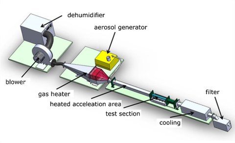
A study on aerosol transport was performed during the project STAUB-I, to analyse the driving parameters for particle transport in a gas flow. The operation experience of previous HTRs with its limited resources on dust transport and its safety relevance was analysed. Two test facilities were designed for experiments to gain the needed information for a detailed and validated model. In addition CFD-Simulations were performed at Helmholtz-Zentrum Dresden-Rossendorf to support the test facility conception. |

Figure 2: Concept of a designed test facility
