AMTEC-D
Table of contents
AMTEC-D: Development of an alkali metal thermal to electric converter for highly efficient direct conversion of heat into electricity
|
Project manager: |
Prof. Dr.-Ing. habil. Antonio Hurtado |
|
Contributor: |
Dipl.-Ing. Martin Zwicker |
|
Duration: |
03/2017 – 06/2021 |
|
Funding: |
European Union (EFRE) and the Free State of Saxony |
|
Funding code: |
100240811 |
|
Cooperations: |
|
Joint project coordination:
Technische Universität Dresden - Chair of Hydrogen and Nuclear Energy
Brief Description
The aim of the research project is to develop a highly efficient, environmentally friendly and economically competitive alkali metal thermal to electric converter (AMTEC) using advanced ceramic materials and innovative laser processes.
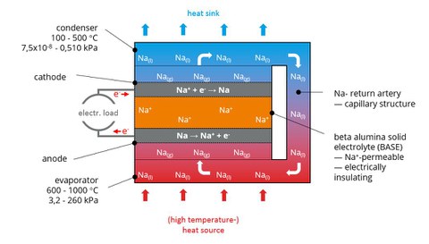
An AMTEC is a thermochemical system that converts a heat flow directly into electrical energy. Fig. 1 shows the basic principle.
The converter essentially consists of a hermetically sealed volume containing a defined amount of alkali metal, preferably sodium (Na) or potassium (K). Since the pressure in this volume is lower than in the environment (partial vacuum), the alkali metal boils at comparatively low temperatures. The working volume is separated into two partial volumes by a ceramic membrane (Beta-Alumina Solid Electrolyte, BASE). This membrane is only permeable for alkali ions and has an insulating effect against electrons. In addition, this membrane is coated on each side with an electrically conductive electrode.
If the temperature is increased in a partial volume (heat input), the alkali metal vaporizes there and thus generates a high alkali metal vapor pressure. Since the other partial volume is kept at a lower temperature (heat conduction), a pressure difference is created above the separating membrane, which favors the transfer of the alkali metal to the side of the lower pressure. However, since the alkali metal can only diffuse through the membrane in an ionized condition, there is one electron per atom on the inlet side of the BASE (anode) and one electron per atom on the outlet side (cathode). The electrons are conducted through an external circuit and can be tapped as usable electrical energy.
Fig. 2 schematically shows the structure and function of an AMTEC. In order to keep the pressure difference large, the temperature on the cold side is kept so low by appropriate cooling that the metal vapor diffused through the membrane condenses on the cooling side. The liquid metal is then transported back into the evaporator volume via a wick (porous ceramic, steel capillary) or an electromagnetic pump. This closes the internal circuit. The fundamental advantage of an AMTEC is that it has an internal, regenerative thermochemical cycle that does not require any moving machine parts. This makes it largely independent of the type of energy source used. Only a sufficiently large temperature difference must be available.
History
The AMTEC technology was first published in 1968 in a US patent. In the 1980s, the technology was further developed with the aim of being used in space missions. In the 1990s, NASA intensified research work, in particular. The development resulted in several demonstrators as well as in the use of such devices in space missions. A radioactive alpha emitter (e. g. plutonium) was mostly used as a heat source. Thus, a constant energy supply of the aircrafts for several decades could be secured for long-term missions. The modular design makes it easy to adapt the devices to the required performance range of the probes. During the last decades, the work was continued continuously for space travel. The US company Advanced Modular Power Systems (AMPS) built several facilities and tested them under space conditions. It documented error-free running times of more than 8,000hours with a useful electrical output of 6 to 10 W and a voltage of >3 V. The devices thus achieved a conversion efficiency of 14 to 18 %.


