Triaxial testing machine

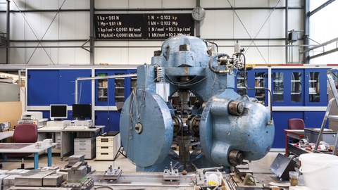
Triaxial testing machine at TU Dresden
With the triaxial testing machine, in short: “Triax”, loads can be introduced into a test specimen in all three spatial directions. The Triax is the oldest testing machine in the Otto Mohr Laboratory. It was constructed in the early 1970s and is one of the few of its kind in the world. The machine consists of a cast steel body weighing approx. 16 t, which encloses all three loading axes.
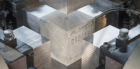
Each loading axis is equipped with a hydraulic cylinder having a load capacity of 5,000 kN pressure or 200 kN tension, which also allows the investigation of (ultra) high-strength concretes. The cylinders can be controlled individually. Both force and displacement control are possible. The testing machine can be used to apply one-, two- and three-axial compression as well as compression-tension or tension-tension combinations to a specimen. Various load introduction devices are available. Brushes made of high-strength steel are preferably used as these hinder the transverse extension of the specimens much less than rigid load introduction plates. Standard specimens for multi-axial compression tests are cubes with 10 cm edge length. For disc-shape specimens for uniaxial and biaxial loading, edge lengths of 20 × 20 × 4 cm are possible. The specimens can be made of pure concrete, but also with reinforcement. For the introduction of tensile forces into reinforcements, special load introduction constructions usually have to be developed.

Concrete cube with embedded fiber optic sensor surronded by load introduction brushes
The measurement technique, especially for triaxial tests, is a challenge. How can you record deformations on a test specimen that is covered on all sides by load introduction devices? The preferred solution are embedded fibre-optic sensors that record the deformations inside the specimen. In addition, inductive displacement transducers are used to measure the transverse deformation of the steel bristles of the load brushes during loading.
The metrological recording of deformations is possible with several other methods if the test specimens are only subjected to uniaxial or biaxial loading. Since two or four sides of the specimen are then unloaded, the deformations can be recorded with strain gauges, displacement transducers and also optically with a photogrammetric measuring system (GOM). By using partly complementary measuring techniques, a holistic load-bearing and failure behavior of the test specimen can be determined and crack formation processes can be documented.
| Technische Informationen | Technical information | ||
| Max. statische Prüflast | Max. static test load | Druck | Compression | 5.000 kN |
| Zug | Tension | 200 kN | |
| Max. Kolbengeschwindigkeit | Max. piston speed | 1 Zylinder | Cylinder | 190 mm/min |
| 2 Zylinder | Cylinders | 95 mm/min | |
| 3 Zylinder | Cylinders | 63 mm/min | |
| Maximaler Maschinenweg je Achse | Maximal lift of the hydraulic cylinder per axis | 100 mm | |
| Zubehör | Accessoires | ||
|
||
