Wärmestromdichte-Versuchsanlage
heat flux density test facility
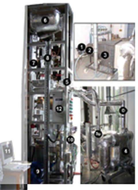
1 gas burner
2 combustion chamber
3 radiation chamber
4 membrane wall segment with circulation loop
5 quench
6 drum
7 double-pipe heat exchanger
8 electrical heating cartridge
9 vortex flow blower
10 MSR technology
11 measurement unit
12 switchboard
Sp feed water (input membrane wall segment)
D steam (output membrane wall segment)
The heat flux density test facility (WSD-VA) represents the model of a large scale steam generator in the laboratory and therefore mainly serves:
- Validation of online heat flux density measures by balancing,
- Test of effective heat conductivity of wall constructions,
- Investigations on thermomechanical behavior of refractory products,
- Investigations on the influence of coatings situated on membrane walls or on refractory products on heat exchange, and
- Evaluation of radiation properties of different coating states.
The core of the test facility is a heated, water permeated membrane segment, where heat flux density can be determined by identification of the corresponding temperature differences between the tube crown and the bordering tube web. At the same time, input power is calculated with by temperature difference and the volume flow of the working fluid with the help of a calorimetric process (heat balance), and is used for the purpose of validating the heat flux density determined beforehand by the system’s characteristic curves.
The membrane walls superstructures mostly consist of several layers (tube wall tiles with rear casting mass, laser-cladding layer and others), of which the single thermal conductivities can be easily determined or are known, but at large the effective conductivity of the wall superstructure is not readily measurable. Uncertainties of mathematic models of such wall superstructures can therefore also be checked.
Mechanical tensions occur when heating up, because the thermal expansion coefficients of the delivered wall construction material used differ. Depending on the construction of the linings, the occurring tensions can partly be removed if there is a certain possibility of relative movement between the single components. With the help of the test facility, investigations on deformation behavior can be performed.
Experiment operation and measure possibilities
facility control
The test facility is only partly automated in order to achieve highest possible flexibility. This includes a safety chain for burner operation, control of electrical heat cartridges (preheating system), as well as control of the drum fill level. (heating circuit). The heating power of the burner, the combustion chamber temperature and die circulating volume of water or the resulting amount of steam can be adjusted by hand.
Investigation possibilities, data logging and evaluation in the laboratory.
The following can be investigated::
- Thermal properties of various wall constructions (linings, hardfacing layers, coatings and others)
- Radiation properties and surface temperatures of coatings with the help of high speed infra-red cameras
- Various gas atmospheres in gaps between rear-ventilated plates
- Thermally induced mechanical tensions, and
- Signalling characteristics of changing coating situation
A high-speed infra-red camera, a hydrometric vane for volumetric flow measurement, pressure sensores and thermocouples for absolute temperatures or temperature differences between tube webs and tube crowns are available for data logging. The data are summarized by a data logger and stored, presented and, if necessary, calculated by a data collecting facility. Additional evaluation is also possible in our physiochemical laboratory.
Technical parameters
| Burner capacity: | 12 up to 50 kW (infinitely adjustible) |
| Secondary air: | up to 50 Nm³/h (infinitely adjustible) |
| Gas temperature: | up to 1.500 °C |
| Feed water temperature: | 90 °C |
| Power of electrical heating cartridges: | 3 x 3 kW |
| Power of calibration heating cartridge: | 3 kW |
| Circulation quantity: | 2 up to 20 l/min (infinitely adjustible) |
| Tube outside diameter of membrane wall: | 57 mm |
| Tube length membrane wall: | 500 mm |
| Membrane wall divide: | 75 mm |
| Recirculation loop: | DN 100 |
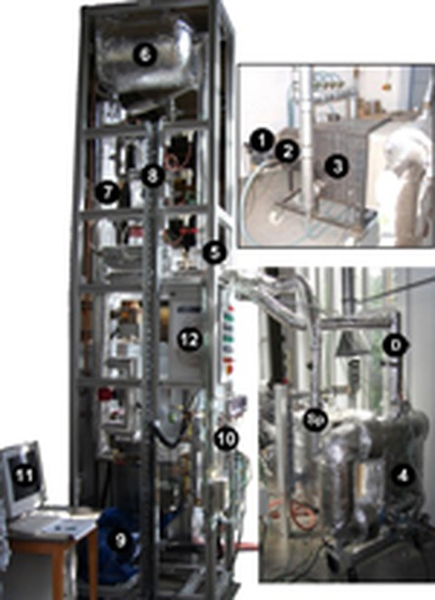
1 gas burner
2 combustion chamber
3 radiation chamber
4 membrane wall segment with recirculation loop
5 quench
6 drum
7 double pipe heat exchanger
8 electrical heating cartridge
9 vortex flow blower
10 instrumentation and control technology
11 data collecting facility
12 switchboard
Sp feed water (input membrane wall segment)
D steam (output membrane wall segment)
Heat flux density test facility


