Subproject B5
Load carrying behaviour of the bond of textile reinforcements and basic research on details of constructive reinforcements
Director
Dr.-Ing. Regine Ortlepp
Institute of Concrete Structures
Staff
M.Sc. Enrico Lorenz
Aim
Basic research on force transmission between textile reinforcement and fine grained concrete matrix is the main objective of subproject B5. The focus is on structurally important details such as end anchorage or overlaps of the textile reinforcement.
The description of the bond behaviour between textile reinforcement and fine grained concrete matrix is the first goal of subproject B5 with the quantification of influences like the surface structure of filament yarns within the textile, the composition of the coating, the fibre materials, the mineral matrix or the layer thickness of the fine grained concrete matrix being at the centre of the examinations.
The description of force transmission in end anchorage and overlaps is the second objective. It is the aim of the computational approach to determine the required end anchorage and overlap length for selected textiles in dependence of the bond stress-slip-relation.
The prerequisite for the applicability of the computational approaches is the definition of certain limiting conditions which have to be kept. These conditions specify when bond failure between the textile reinforcement and the surrounding fine grained concrete matrix can be excluded. One example is a minimum layer thickness for the transfer of bond forces from the textile into the fine grained concrete matrix. This requirement prevents the delamination/longitudinal matrix splitting of the reinforcement layers which results from exceeding the tension ring´s load carrying capacity.
In certain areas of reinforced structural components the bond length of the textile reinforcement has to be as short as possible. An example for this requirement is the shear strengthening of T-beams. In this case, the anchorage of the textile reinforced strengthening layer has to be placed between the last shear crack and the bottom edge of the slab (see Subproject T3 and Transfer Project T3). The increased use of carbon fibres, which have larger anchorage lengths than glass fibres, causes the need for constructive solutions on how to reduce anchorage lengths. Furthermore, it has to be researched in how far the bond of textile reinforcements can be improved in the anchorage area. For example, apart from using geometrical sensible ways of anchorage, such as loops, the bond properties can be changed by adding an additional coating to the edge areas.
Results
Bond Tests
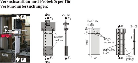
The test setup for carrying out textile pull-out tests with short anchorage lengths developed by KRÜGER was specifically modified and further developed for testing coated carbon reinforced textile fabrics. Toward this aim, the sample was extended in the upper area and the upper short anchorage length lE was adapted to the properties of the respective textiles. The upper anchorage area was fixed at simple or multiple distances of the respective weft threads to determine the bond properties of textile yarns. However, 30 mm should not be exceeded so that a short anchorage length can be ensured. The anchored lower section has to be distinctly enlarged to guarantee sufficient anchorage length without displacement of the anchored yarn end. In the further course, the force-crack opening-relations, which have been determined in the textile-pull out tests, constitute the basis for the arithmetical determination of the bond stress-slip-relation.
Figure 1: Test set-up
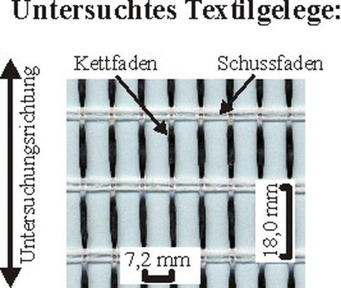
The experimental bond tests serve to determine the force-crack opening-relations for the different warp knitted fabric structures used in the CRC. The image shows an example for a biaxial fabric. In warp direction, it consists of carbon filament yarn from the Toho Tenax Europe GmbH with a fineness of 800 tex. The centre distance is set uniformly at 7.2 mm. In weft direction, alkali-resistant glass fibres of the Saint-Gobain Vetrotex Deutschland GmbH with a fineness of 640 tex and a distance of 18.0 mm were processed. The textiles were modified by a subsequent polymer based coating. The coating content is set at 15.0 mass percent.
Figure 2: Textile
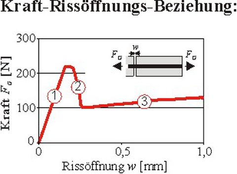
The textile pull-out tests result in a stress-crack opening-relation which was determined as the average value of eight tests. The individual bond areas can be clearly discerned in the force-crack opening-relation of the exemplary textile which was made from coated carbon fibres. While the adhesive tensile bond is activated in section 1, which is increasing, the adhesive tensile bond is destroyed and the yarn detaches from the fine grained concrete matrix in section 2, which is decreasing. In the subsequent third section the remaining pull-out force, which amounts to approximately 50% of the maximum value, is furthermore only determined by friction. Several influences lead to a further increase of the yarn pull-out resistance. These are process related influences from the sewing thread and yarn undulation combined with the coating´s stiffening effect in case of increasing crack opening. Unprocessed yarns, on the other hand, result in a steady decrease of the pull-out resistance in the friction area after the adhesive tensile bond has been destroyed.
Figure 3: Load-Deformation-Curve
Analytical Tests
Determining the bond stress-slip-relation (BSR) based on the measured force-crack opening-relation is the objective of the analytical tests. This is achieved with the help of a model which was adapted to the geometry of the sample. Subsequently, the anchorage length lE which is required to anchor the relevant force F is calculated with the help of the determined (BSR) The following arithmetical examination of the bond problem between filament yarn and matrix was carried out with the help of a slip based model which builds on the multilinear piecewise self-contained solutions to the bond differential-equation by RICHTER from Subproject A3.
The analytical tests for the anchorage problem are based on the assumption that the e module is constant for the yarn and the yarn´s circumference, which has been averaged from the anchorage lengths, is ug = 3.3 mm. The averaged circumference is eliminated in the course of the calculation and, thus, does not have any influence on the final result of the anchorage length. Furthermore, the strain of the concrete matrix is neglected due to its low size.
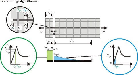
Observing the relative displacements within the crack, the share from the upper part of the sample has to be distinguished from the lower part of the sample in this test setup. In the upper part of the sample failure because of pull out of the filament yarn from the fine grained concrete matrix becomes decisive. Due to the chosen small anchorage length lE of 18 mm, the simultaneous activation of several sections of the (BSR) can be prevented for this strain stiffness, as a rule. Only in the transition zone between the separate linear sections, small sections of two zones of the (BSR) are used at the same time. In each case, a piecewise self-contained solution is possible through a formulation of the function sge,1(F). In the lower section, the mere activation of the adhesive tensile bond in the rising section of the bond stress-slip-relation is necessary to introduce the available pull-out forces. Depending on the yarn pull-out force at the drawn end, the corresponding slip can be calculated from sge,2(F). After the single values of the relative displacements of the drawn ends from the upper and lower section of the sample have been determined, the corresponding crack opening w(F) in the area of the predetermined breaking point, which is the sum of the relative displacements of the loaded yarn ends sge,1(F) und sge,2(F), can be calculated.
Figure 4: Calculation algorithm
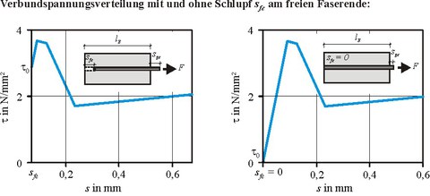
In a second step, the anchorage length lE can be determined with the help of the calculated partly linear VSB. It states which anchorage length is required to anchor a specific Force F depending on the slip at the pulled end of the fibre sge. With the help of the VSB, the required anchorage length can be calculated for end anchorage as well as for continuous reinforcements with a zero point of the displacement at the end of the required load introduction length by varying the initial value ?0.
Figure 5: Bond stress distribution
Anchorage Lengths of textile reinforcements
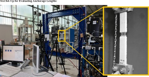
The comparative experimental check of the analytically determined anchorage lengths is carried out by using the test setup for the direct determination of the anchorage length which has been developed in Subproject C3. Toward this aim, the sample´s shape has been modified for testing a constant anchorage length.
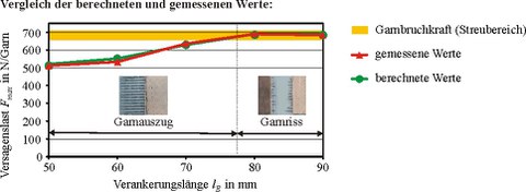
Figure 6: Achorage lengths - Comparison
The results of the performed tests for the determination of the anchorage length have been presented as averaged value from four single samples each. While filament yarns, which have been sufficiently integrated, with load introduction lengths of = 80 mm result in fibre cracking, anchorage lengths of = 70 mm cause fibre pull-out. The average fibre pull-out force amounted to approximately 680 N. The anchorage lengths, which were analytically determined from the force-crack opening-relation, have been depicted comparatively to the experimental values. The calculated failure load agreed satisfactorily with the experimentally determined results and the respective anchorage lengths. Consequently, the highly time-consuming experimental tests for the determination of end anchorage lengths are, furthermore, only necessary to spot-check the analytically calculated load introduction lengths.
Anchorage Elements
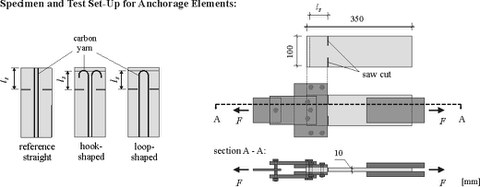
Attempts to determine the effects of geometrical anchorage elements were based on anchorage methods from reinforced concrete constructions by built-in unprocessed filament yarns in the shape of hooks and loops. The sensibility of a further development or implementation in the manufacturing of textile reinforcements was examined. The tests were carried out with the help of the test setup for pull-out tests. The examined bending radius of the anchorage elements was set at 15 mm. The examined samples´ anchorage length lE, starting at 25 mm was increased until the place of failure was shifted into the area outside the anchorage.
Figure 7: Test set-up
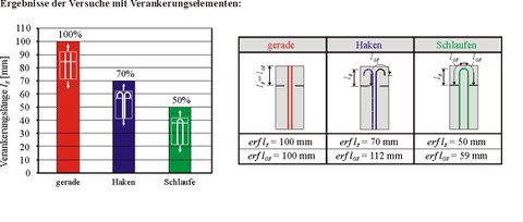
Regarding the determined minimum anchorage length, a general reduction of the required development lengths could be achieved through a hook and loop-shaped arrangement of the filament yarns. While comparable yarn ends which were anchored straight required an anchorage length of 100 mm, the use of anchoring hooks caused a 30% reduction of the necessary bond length. The use of loop-shaped elements even resulted in a 50% decrease of the required load transfer area in force direction compared to the reference yarn which was anchored straight.
Figure 8: Results
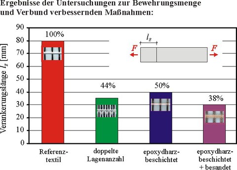
Examinations also showed a positive impact of bond improving measures and an increase in the degree of reinforcement in the anchorage area. Compared to the reference textile, which had not been modified, an additional epoxy resin coating and epoxy resin with sanding caused a reduction of the required development length of 50 to 60%. The fabrics which were coated with epoxy resin and sanding caused the most significant reduction of the required anchorage area which could be reduced to 40% of its initial size.
Figure 9: Coating
overlapping lengths
Usually, overlaps cannot be avoided when strengthening structures with textile reinforced concrete (TRC). Due to the two-dimensional structure of the textile fabrics as well as the composite being produced in layers, overlaps are normally implemented as two-ply joints Overlap tests were carried out with one overlap at the centre of the sample to investigate the load-carrying behaviour of such joints experimentally. The overlap tests followed the uni-axial tension tests (so-called strain specimen tests) which have already been well established. Generally, a bond failure of textile reinforced concrete can occur in different ways. In connection with the overlaps, two failure mechanisms can be observed. On the one hand, failure can happen due to the threads being pulled from the fine grained concrete matrix. On the other hand, failure can also be caused by delamination/longitudinal matrix splitting within the overlap.
Figure 10: Test set-up
The overlap lengths are directly influenced by the extent of bond forces in the limit state of yarn pull-out. That means the required overlap length shortens when the transferable bond forces between yarn and matrix increase (e.g. by increasing the amount of coating to the textile reinforcement). The probability of bond failure by delamination is determined by those lateral tensile forces which result from load introduction and transmission within the overlap. Once the concrete´s tensile strength has been exceeded in the TRC layer, initially small longitudinal matrix splits develop at the beginning of the overlap. Under increased load these splits travel further into the overlap area and may, subsequently, lead to failure. Based on the test results and the observed failure mechanisms a model was developed which can be used to accurately predict the required overlap lengths in the limit state of yarn pull-out. Furthermore, extensive analytic investigations were carried out to predict the probability of delamination failure. The obtained results yielded good correspondences with the values determined in the tests. Moreover, the tests and observations were used to define new requirements for the further development and optimization of the textile-matrix-system. These changes are currently applied with promising results.
Publications
2011
- Schladitz, F.; Lorenz, E.; Jesse, F.; Curbach, M.: Usilenie Tekstilynym Betonom Schelesobetonnoi Konstrukzii Kryschi Istoritschkogo Sdanija. Beton i Zhelezobeton 1 (2011), S. 27-30
- Curbach, M.; Ortlepp, R.: Leichtes Bauen mit ultrahochfesten und Textilbetonen. In: Bauforschung und Baupraxis, Heft 10: “Wie wollen wir in Zukunft bauen?” – Festschrift zum 60. Geburtstag von Prof. Dr.-Ing. Wolfram Jäger, Dresden, 19.04.2011. S.17-22 - ISBN 978-3-86780-216-1
2010
2009
- Lorenz, E.; Ortlepp, R.: Berechnungsalgorithmus zur Bestimmung der Verankerungslänge der textilen Bewehrung in der Feinbetonmatrix. In: Curbach, M. (Hrsg.), Jesse, F. (Hrsg.): Textile Reinforced Structures : Proceedings of the 4th Colloquium on Textile Reinforced Structures (CTRS4) und zur 1. Anwendertagung, Dresden, 3.-5.6.2009. SFB 528, Technische Universität Dresden, D–01062 Dresden : Eigenverlag, 2009, S. 491+502 – ISBN 978-3-86780-122-5 URN: urn:nbn:de:bsz:14-ds-1244049857647-62309
- Ortlepp, R.; Brückner, A.; Lorenz, E.: Verbundversagensmechanismen im Verankerungsbereich von textilbewehrten Feinbetonverstärkungsschichten. In: Curbach, M. (Hrsg.), Jesse, F. (Hrsg.): Textile Reinforced Structures : Proceedings of the 4th Colloquium on Textile Reinforced Structures (CTRS4) und zur 1. Anwendertagung, Dresden, 3.-5.6.2009. SFB 528, Technische Universität Dresden, D–01062 Dresden : Eigenverlag, 2009, S. 433-446 – ISBN 978-3-86780-122-5 URN: urn:nbn:de:bsz:14-ds-1244049139702-05245
- Ortlepp, R.; Lorenz, E.: Anchoring of textile reinforcements in a fine-grained concrete matrix.In: Kuczma, M. (Hrsg.); Wilmanski, K. (Hrsg.); Szajna, W. (Hrsg.): Proceedings of the 18th International Conference on Computer Methods in Mechanics – CMM2009, Zielona Góra, 18.–21.5.2009. Zielona Góra : The University of Zielona Góra Press, 2009, S. 347–348 – ISBN 978-83-7481-245-0
- Lorenz, E.; Ortlepp, R.: Basic research on the anchorage of textile reinforcement in cementitious matrix. In: 9th International Symposium on Fiber-Reinforced Polymer Reinforcement for Concrete Structures (FRPRCS-9), Sydney, 13.-15.07.2009. – Book of Abstracts, p. 136 and CD-ROM – ISBN 978-0-9806755-0-4

