Preliminary work for SP C3-L6-II: Strut-and-tie models and torsion
Table of contents
Project data
| Titel | Title Vorarbeit zum TP C3-L6-II: Entwurf und Bemessung von Carbonbeton-Bauteilen mit Stabwerkmodellen und für Torsionsbeanspruchungen im Verbundvorhaben C3-L6: Bemessung und bauliche Durchführung | Preliminary work for SP C3-L6-II: Design and Dimensioning of Carbon Reinforced Concrete Components with strut-and-tie models and for torsional stress as part of the joint research project C3-L6: Dimensioning and construction Förderer | Funding Bundesministerium für Bildung und Forschung (BMBF) / C³ – Carbon Concrete Composite Zeitraum | Period 01/2019 – 03/2021 Verbund- und Teilvorhabenleiter | Leader of the joint and subproject Prof. Dr.-Ing. habil. Ulrich Häußler-Combe Bearbeiter | Contributor Ahmad Chihadeh M.Sc. Projektpartner | Project partners Lehrstuhl und Institut für Massivbau der RWTH Aachen | Betonwerk Oschatz GmbH, Oschatz | DYWIDAG-Systems International GmbH, Unterschleissheim | Halfen GmbH, Langenfeld/Rheinland |
Report in the annual report 2019
STRUT-AND-TIE MODELS FOR CARBON REINFORCED CONCRETE

3D Model of a carbon reinforced concrete deep beam
The Strut-and-Tie Model (STM) is one of the main methods used for structural analysis and the design of steel reinforced concrete. The investigation of its applicability on carbon reinforced concrete becomes imperative. Such investigation is in progress in one of the subprojects of the joint research project C3-L6 “Structural calculations and training”.
A typical structural element, where the STM is applied, is the deep beam. Therefore, a model is being developed to simulate the behaviour of the carbon reinforced concrete deep beam. The in-house software “CaeFem” is used to implement the simulation. The numerical simulation of the beam will then be compared with the results of experimental tests on the beam. The test specimens have a different amount of reinforcement and different sizes of the supports to obtain different modes of failure which are concrete compression failure, bar tensile failure, and anchorage failure.

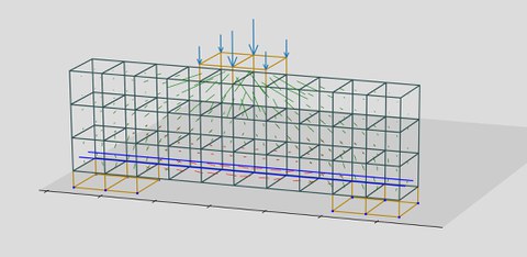
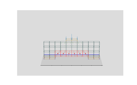
Crack‘s surfaces and orientations obtained from a simulation of carbon reinforced concrete deep beam using Strong Discontinuity Approach (SDA)
Two and three-dimensional models are conducted based on the number of bars used in the experimental tests. The bars are embedded in the surrounding solid elements representing the concrete matrix. The bars and the solid elements are coupled together by bond elements allowing for the independent discretization of bar elements with respect to solid elements. This simplifies the meshing process and gives the ability to choose bar elements and continuum elements with different dimensions.
Different material models are being implemented as well. In addition to the Strong Discontinuity Approach, isotropic damage, plastic-isotropic damage, and micro-plane anisotropic damage have been considered. The results obtained from the experimental tests are used for the verification of the result of each material model.
Report in the annual report 2018
STRUT-AND-TIE MODELS FOR CARBON REINFORCED CONCRETE

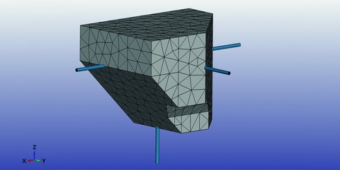
3D-Modell eines Beton-Knotens als Stabwerkmodell mit drei eingebetteten Stäben
Strut-and-tie models (STM) are widely used in the analysis and design for steel reinforced concrete elements. This is also expected when using carbon reinforcement. Hence, an investigation is required to verify the applicability of STM on carbon concrete. What set carbon bars apart from steel bars, with relation to the topic, is mainly the ductility and bond stress. STM consists of struts subjected to compression, ties subjected to tension, and nodes connecting struts and ties in which different forces in different directions meet together and equilibrate each other. Therefore, nodes are subjected to multi-axial stresses and also they are the most stressed areas in an STM.

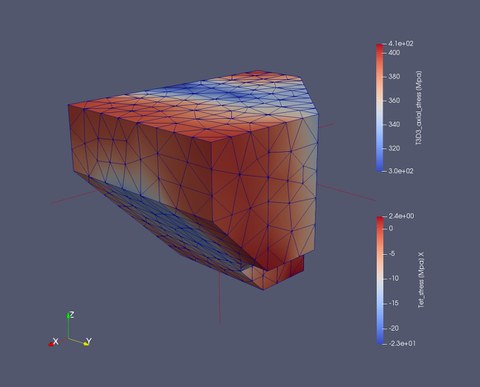
Spannungen am 3D-Knotenmodell in X-Richtung. Der Knoten wird durch die Flächen begrenzt, welche den Stäben ausgesetzt sind
For these reasons, analysis of nodes was carried out using a finite element simulation. As a first step, a 2D model for compression node was implemented. Followed by several models for different node types and geometries ending up modelling a node in a 3D STM from the so-called “Thin-Walled Tube, Space Truss Analogy” method used for torsional analysis. Bars embedded in a concrete body were subjected to tensile forces. These bars are the longitudinal and stirrups reinforcement. The application of compression forces has been done by applying nodal constraints and nodal forces. This is to avoid rigid body motion.
The model was implemented by using embedded bars inside tetrahedral solid elements representing the concrete matrix. Bond elements were used to connect bars to the surrounding concrete. It is important to notice that the bar elements and the surrounding tetrahedral solid elements have no common nodes. This makes the discretization simpler as it gives the possibility to define the mesh of the concrete and the mesh of the bars independently. Bars in y and z directions represent the stirrup, and as a stirrup is made from bent rebar, they have a common node where the hook is supposed to be. This decreases significantly the bars slippage due to lateral constraints. The outputs of the simulation are 3D spatial stresses, axial stresses in the bars, nodal displacements and forces as well as bond stresses corresponding to slip values.
