MABET
Table of contents
Project data
|
Titel | Title |
Report in the annual report 2021
Plasticity measured and modelled
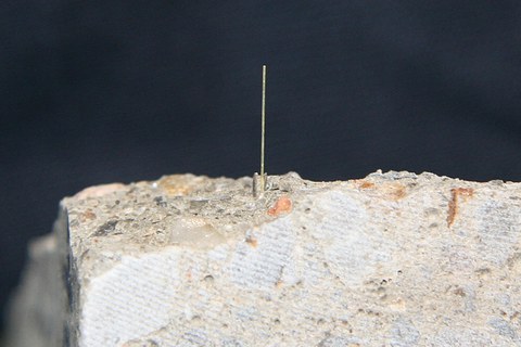
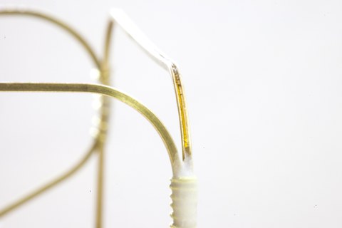
Fibre optic sensor after the fracture of the concrete
In the triaxial testing machine, concrete specimens were loaded and unloaded several times at different load levels under uniaxial, biaxial and triaxial compression. The degradation took place under stress conditions on the compression, tension and shear meridians, whereby the change in shape qualitatively corresponded to the change in shape under the eponymous uniaxial load. Fibre-optic sensors were integrated into the concrete by using a support frame made of brass U-profiles. The strains were thus measured during the complete loading and unloading cycles in all three directions and the stiffness after pre-damage was also determined in the individual directions.
Using these new experimental findings regarding plastic deformation development and ductility, Dr. Vogdt (TU Berlin) extended and validated a distortion- and energy-based material law established by Prof. Petryna. Some assumptions that are often made when implementing previous material models were refuted by the measurement data. For example, a volume constancy or a constant dilatancy during the plastic deformation development could not be confirmed. Rather, the plastic deformation development depends on the existing confinement and the degree of loading of the concrete sample. This is so significant because it concerns the fundamental variable of the plasticity theory. All other variables are derived from the simulated plastic deformation state.
The plastic deformation development was thereby empirically determined and a new yield rule was derived. A new hardening rule also takes into account that ductility depends on confinement under different three-axial stress ratios. The resulting plasticity law is able to represent different triaxial compression tests with different stress ratios without the need to adapt the model parameters to the different tests. This circumstance offers a significant improvement over previously used concrete models. The proposed evolution equations are intentionally formulated in general terms so that they can be used in the future for adapting existing concrete material models by replacing the evolution rules they contain.
Report in the annual report 2020
Measurable anisotropy after loading
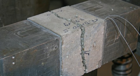
Determination of the tensile strength to characterise the structural deterioration
Under load, concrete shows signs of damage that are oriented according to the applied load. This load-induced anisotropy is captured by a strain- and energybased material law established by Prof. Petryna (TU Berlin). The values for validation are determined in the triaxial testing machine at the IMB. The strains are measured with fibre-optic sensors (FOS), which are positioned in the concrete on a support frame made of brass U-profiles.
The tensile strength is a suitable parameter for characterising the damage. However, from an experimental point of view – in contrast to loading and unloading under compression – the tensile strength can only be determined once on a test specimen. The focus was therefore on the direction in which the concrete elongated during the multi-axial pre-damage. Stress ratios with equal elongation in two directions (compression meridian), as well as elongation in one direction (tensile meridian), were selected. The elongated directions were unloaded or loaded with 5% of the compressive force in the compressed directions. The pre-damage was carried out with 80% of the failure load under the respective stress ratio. Pre-damage of all specimens was done first before the triaxial testing machine was converted to the tensile configuration. The test specimens were
about 70 days old at the time of the tensile test. It had to be noted that the measurement quality of the FOS had deteriorated considerably in some specimens since the preloading. This is due to the low alkali resistance of the measuring fibres. On the other hand, the uniaxial tests allowed additional measuring fibres to be applied to the free surfaces.
Although relatively brittle high-strength concrete was tested, the localisation of the cracks was often clearly visible in the measured values before the tensile fracture. The tensile strengths obtained were compared with those of undamaged reference specimens. Pre-damage with elongation in two directions led to a reduction of about 10%. If, on the other hand, the elongation during preloading was concentrated in one direction, the tensile strength in this direction was reduced to about half. With a supporting lateral ompression in the elongated directions, not only the multi-axial strength increases but also the associated elongations and damages, which is why the remaining tensile strength tends to decrease somewhat more than in specimens without lateral compression.
Report in the annual report 2019
From cube to cuboid
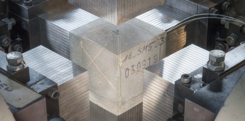
Test specimen with fi ber optic sensor in triaxial testing machine
As the load increases, the damage in concrete also increases, and it shows plastic deformations, which are oriented according to the applied load. For example, cracks form perpendicular to tensile stresses or parallel to compressive stresses. As a result, concrete no longer behaves isotropically after a certain load, but it shows different values of stiffness, plastic deformation and strength in the various directions.
A strain- and energy-based material law formulated by Prof. Petryna (TU Berlin) is able to describe this load-induced anisotropy. The parameters required for validation of a high-strength concrete are determined at the Institute of Concrete Structures in a triaxial testing machine. The strain measurement is carried out using fibre-optic sensors which are positioned in the concrete on a support frame made of brass U-profiles.
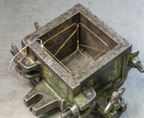
Positioning of the fibre-optic sensor in the formwork using a brass profile support frame
In uni-, bi- and triaxial compression tests, the relevant strain conditions for different stress ratios are investigated: compression in one direction, elongation in two directions (compressive meridian), compression in two directions, elongation in one direction (tensile meridian) and compression or elongation in one direction each, and negligible compression in the third direction (shear meridian). The load was applied proportionally in all load directions and stepwise at load levels between 30% and 95% of the strength. After each level, the load was removed which again was done proportionally or separately according to deviatoric (sum of stresses constant) and hydrostatic (all stresses equal) stress components. The remaining strains were disproportionately large compared to the elastic strains, especially in the elongated directions. In some cases, plastic strains of more than 5% were measured, showing that the original cube had apparently become a cuboid.
In addition, the test specimen was subjected to three uniaxial compression tests with a low load between the load levels to determine the remaining loading and unloading stiffness in all directions. Along the direction of the applied compression forces, the stiffness remained almost constant over nearly all load levels, while in the direction along the elongations, it decreased in some cases to a quarter of the initial stiffness. Therefore, it was possible to quantify the load induced anisotropy experimentally.
Report in the annual report 2018
Fiber optic sensors in concrete
Faseroptische Sensoren, eingebettet in einem Trägergerüst aus Messing-U-Profilen
Prof. Petryna (TU Berlin) is aiming for a realistic modelling of concrete behaviour by applying a strain- and energy-based formulation of the material law. This requires quantitative determinations of the load induced anisotropy. The model parameters are to be derived comprehensibly from direction-dependent stiffnesses, strengths and plastic deformations determined by measurements. Therefore, experiments with different loading and unloading paths with partly changing loading directions in the three-axial stress space are planned. Since the side surfaces of the test cubes are loaded simultaneously or successively by the load introduction medium, they are not available for the application of measurement technology. The choice, therefore, went to fibre-optic sensors (FOS), which measure the strain continuously along their axis and which are positioned in the concrete by means of a support frame.
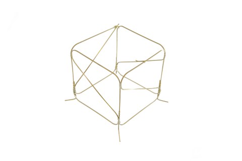
Trägergerüst aus Messingprofilen zur Positionierung des faseroptischen Sensors im Beton
The suitability of the measuring system in concrete was proven in preliminary tests on mortar samples. The evaluation criteria were comparisons with established measuring devices such as strain gauges and photogrammetry. Glass fibres with acrylate coating only provided satisfactory results if they were installed directly in the concrete. However, this is difficult to achieve with regard to the position fixing and protection of the fibres during casting. In contrast, glass fibres with a polyimide coating show high-quality results, regardless of the type of glue used, or the presence of glue or the brass profile at the measuring point. In addition, they have a smaller turning radius than acrylate-coated glass fibres.
Based on these findings, a fibre alignment system was developed for the cube-shaped test specimens with four measuring points per direction. After optimizing the manufacturing process - after all, the sensor fibres have to survive concrete casting and grinding of the surface - the suitability of the measuring system could also be demonstrated in the first two- and three-axial tests. As in the preliminary tests on mortar prisms, no influence on the strength by the supporting structure could be determined.
Report in the yearbook 2017
Discover anisotropy with fibers
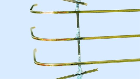
Fibre optic sensors embedded in a support frame made of brass U-profiles; the location of the measuring points is indicated by the red and blue coloured areas
Concrete is almost an isotropic material after its production. But when it is loaded to a certain load level, (micro) cracks occur in the material. The crack openings are oriented along the controlling stress field. As a result, such cracking leads to anisotropy. Anisotropy has been many times analyzed qualitatively, but there are hardly any quantitative assessments of the associated stiffness and strength. Our project partner – Prof. Petryna from TU Berlin – wants to create a realistic model of the concrete’s behaviour based on a strain or energy based formulation of the material law, where evolution laws and failure surfaces are mainly defined by physically measurable parameters. Therefore, knowledge about the anisotropic properties is necessary.
To determine the needed parameters, several experiments were planned at the institute to map different loading and unloading paths of the triaxial stress. After the test piece was pre-damaged, permanent deformations, stiffness in all spatial directions, and the corresponding strength under selected stress ratios were determined. For example, at a uniaxial pressure test, not only the stiffness after unloading and the plastic deformation along the stress direction were determined, but also the stiffness and tensile strength in the corresponding transverse direction.
Therefore, an exact strain measurement, even in areas with extremely low strain, is essential for the success of the research. Since the load is applied to all surfaces of a test cube, in all three directions, it is not possible to install measuring equipment on the cube surfaces. For this reason, it was decided to use fibre optical sensors. They can be used for continuous strain measurements and positioned within the concrete with the help of a supporting structure. Preliminary testing is being conducted for various type of fibre, coating, deflection radius and adhesive. Furthermore, testing is being conducted to determine if the fibre optical sensors can be encased in concrete without a supporting structure within the measurement area. An optimal measuring configuration should be found, similar to those used in conjunction with established measuring devices, like strain gauge and photogrammetry. Key criteria used in the optimization is the precision that can be achieved for the strain and tensile stress measured under pressure, as well as the small effect that the failure mechanism has on the fibre and supporting structure.
